Sheet metal bending is a manufacturing process used to form metal sheets into desired shapes by applying force. It's a common technique in industries like automotive, aerospace, construction, and electronics.
Here’s an overview of key aspects:
1.Bending Methods
V-Bending: Uses a punch and die in a V-shape (most common method).
Air Bending: The punch doesn’t fully force the sheet into the die, allowing flexibility in angles.
Bottoming/Coining: The sheet is pressed tightly into the die for precise angles.
Wiping: The sheet is bent over a die edge using a wiping punch.
U-Bending: Uses a U-shaped die for channels or U-shaped parts.
Rotary Bending: Uses a rotating die to minimize surface marks.
Roll Bending: Uses rollers to form curves or cylinders (e.g., pipes).
Folding: A clamp holds the sheet while a tool folds the edge (common in panel fabrication).
4. Materials
Commonly bent metals:
Mild steel/Stainless steel/Aluminum/Copper/Brass
Material thickness typically ranges from 0.5mm to 25mm, depending on machine capacity.
5. Design Considerations
Minimum Bend Radius: Depends on material (e.g., aluminum can bend tighter than steel).
Bend Relief: Small cuts at bend edges to prevent tearing.
Hole & Cutout Placement: Keep holes away from bend lines to avoid distortion.
Flange Length: Must be at least 4x material thickness for proper bending.
6. Advantages & Challenges
Pros: Cost-effective, high precision, good for prototypes and mass production.
Cons: Springback requires compensation, risk of cracking in hard metals, tooling costs for complex shapes.
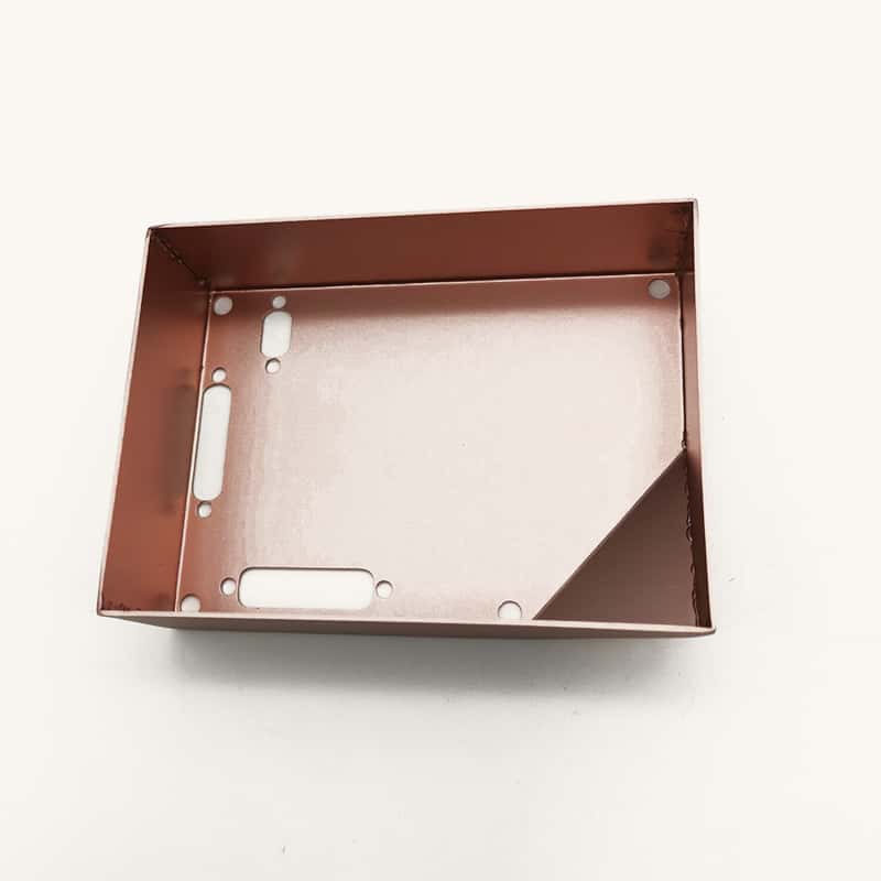
China Sheet Metal Fabrication Manufacturers | Sheet Metal Manufacturers in China
Custom Sheet Metal Parts | Box Sheet Metal | Custom Sheet Metal Enclosures
2. Key Parameters
Bend Radius: The inside radius of the bend (too small can cause cracks).
K-Factor: Ratio of the neutral axis to material thickness (used for bend allowance calculations).
Bend Allowance: The length of the neutral axis in the bend area.
Springback: The tendency of metal to slightly return to its original shape after bending (compensated by overbending).
3. Equipment
Press Brake: Most common machine for precision bending (manual, hydraulic, or CNC-controlled).
Folding Machines: For large panels or box bending.
Roll Benders: For creating curved sections.
Panel Benders: Automated machines for complex bends.
Designing sheet metal bent parts requires careful consideration of material properties, bending processes, and design constraints to ensure manufacturability and functionality. Here’s a step-by-step guide:
1. Understand Sheet Metal Bending Basics
Bend Allowance (BA): The length of the neutral axis between bend lines.
Bend Deduction (BD): The difference between the sum of flange lengths and the flat pattern length.
K-Factor: The ratio of the neutral axis to material thickness (typically 0.3–0.5 for most materials).
Minimum Bend Radius: Depends on material and thickness (e.g., for mild steel, it’s ~1x thickness).
2. Material Selection
Common materials:
Mild steel (low cost, easy to bend)
Stainless steel (higher strength, corrosion-resistant)
Aluminum (lightweight, good for prototyping)
Copper/brass (for electrical/decorative parts)
Thickness: Typically 0.5mm–6mm (thicker materials require larger bend radii).
3. Design Rules for Bending
a) Bend Radius
Use ≥ material thickness (e.g., for 2mm steel, min radius = 2mm).
Sharp bends (< material thickness) may cause cracking.
b) Bend Relief
Add notches or cutouts near bends to prevent tearing (width ≥ material thickness).
Relief depth ≥ bend radius + material thickness.
c) Hole & Slot Placement
Keep holes/slots ≥ 2x material thickness from bend lines to avoid distortion.
For extruded holes, maintain distance ≥ 3x material thickness.
d) Flange Length
Minimum flange length = 4x material thickness + bend radius.
Avoid very short flanges (hard to bend accurately).
e) Bend Direction
Bend lines should be perpendicular to the grain direction (for anisotropic materials like aluminum).
4. Flat Pattern Design
Use CAD software (SolidWorks, AutoCAD, Fusion 360) to generate flat patterns.
Account for bend allowance/deduction based on K-factor.
Include tooling holes for alignment during bending.
5. Tolerances & Dimensional Control
Standard bending tolerance: ±0.25mm (tighter tolerances increase cost).
Springback compensation: Overbend by 1°–5° (depends on material).
Account for variations in material thickness (e.g., ±10% for sheet metal).
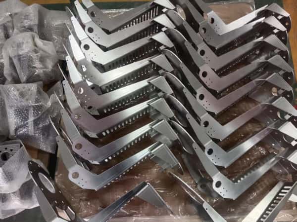
China Sheet Metal Parts Manufacturers | China Sheet Metal Fabrication Factory
6. Manufacturing Considerations
Tooling: Ensure press brake tooling matches bend radius and flange length.
Bend Sequence: Plan the order of bends to avoid collisions with tools.
Deburring: Specify edge finishing (e.g., chamfering) to prevent cuts.
7. Prototyping & Validation
Test with 3D-printed or soft-metal prototypes before mass production.
Check for fit, function, and stress concentrations near bends.
8. Common Mistakes to Avoid
Ignoring bend radius limits → Cracking.
Overlooking springback → Incorrect angles.
Poor hole placement → Deformed features.
No bend relief → Material tearing.
Example Calculation (Simple L-Bracket)
Material: 2mm mild steel
Bend radius (R): 2mm
K-factor: 0.4
Flange lengths: 30mm & 40mm
Bend allowance (BA) = (π/180) × Bend angle × (R + K×T)
For 90° bend: BA ≈ 3.8mm
Flat length = (30 + 40) – Bend deduction (or use BA).
Software Tools for Design
SolidWorks Sheet Metal
AutoCAD Inventor
Fusion 360 (Sheet Metal Workspace)
BendTech (for complex bends)
By following these guidelines, you can design sheet metal bent parts that are both functional and
manufacturable. always consult with your manufacturer for process-specific adjustments!